Small print errors become expensive defects
As boards get denser, pads get smaller and pitches get finer. A print error that goes unnoticed at the first process is carried through placement and reflow, and discovered only when the board already carries its components.
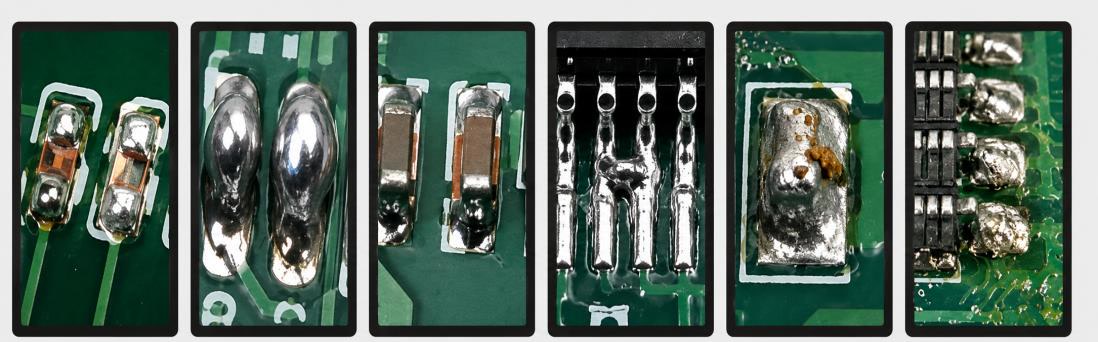
- Too little paste — open or weak joints
- Too much paste — bridges that short adjacent pads
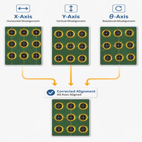
- Misaligned print — placement defects
- Uneven print — rework or scrap of boards that already carry expensive components
Six precision modules
Vision and software only improve yield when the machine can act on them. Each module is designed in-house so that mechanics, controls, vision and software work as one.
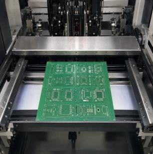 Conveyor & clampingBoard position, width setting and board detection.
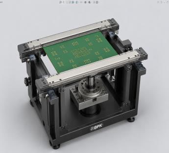 Mask & stencilTension, alignment and board-to-stencil gap control.
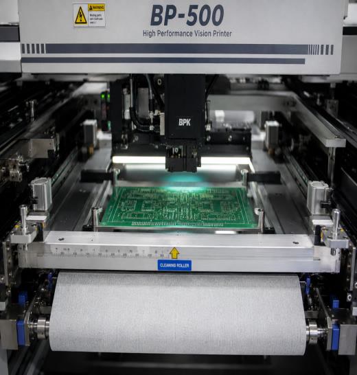 SqueegeePressure, speed and stroke.
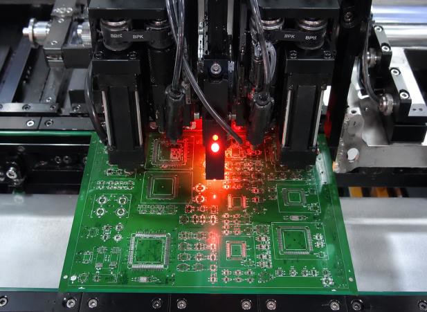 Camera & visionImage capture, fiducial marks and offset measurement.
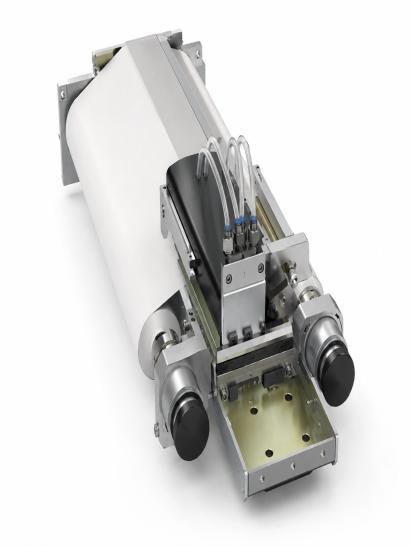 CleanerSolvent, paper and cleaning cycle.
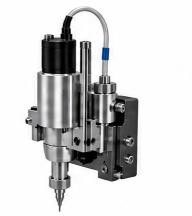 Paste supplyRemaining volume, supply timing and dispensing.
From camera image to machine action
The BP-500 connects vision and sensor data to decisions on the process, and those decisions to the squeegee, paste supply, cleaner and conveyor.
Implemented in the current build
- Fiducial mark recognition
- Board orientation and top/bottom side detection
- QR and DataMatrix code reading
- Camera alignment correction
- Squeegee pressure feedback and paste level sensing
- Board, product, lot and inspection-result traceability
Under development
- Solder paste pattern segmentation
- X/Y print offset detection
- Classification of open, bridged and smeared prints
- Image-based print quality scoring
- Parameter recommendation and automatic correction
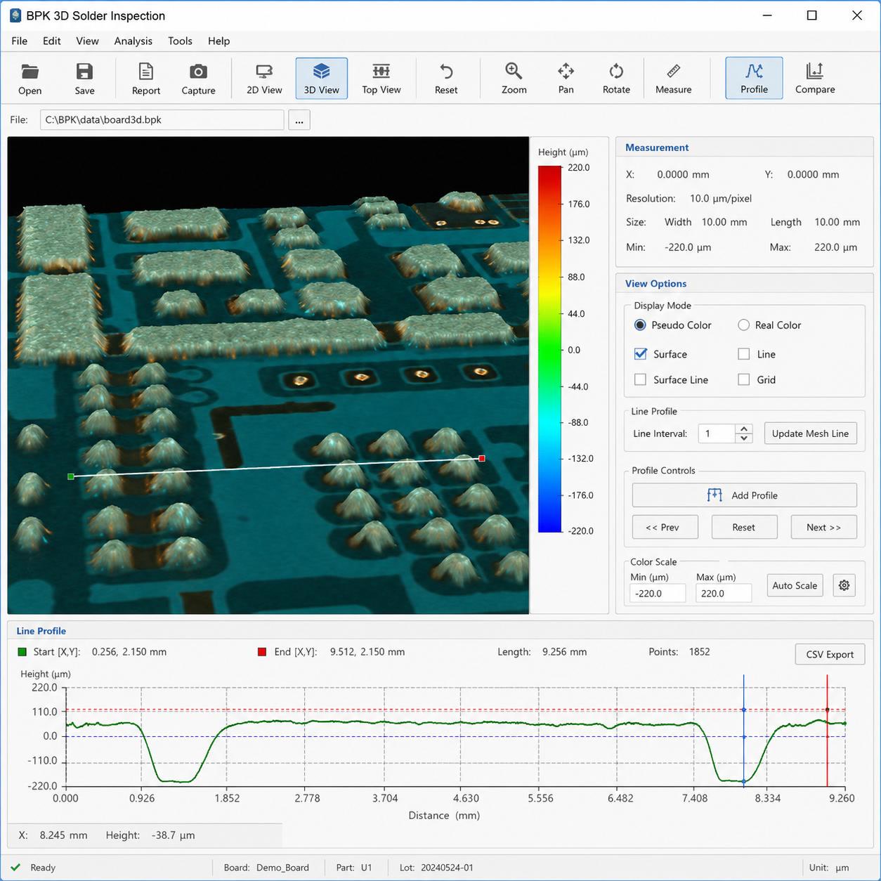
- SPI feedback and predictive maintenance
Validation in factory and site acceptance tests is scheduled with the pilot build.
Want to see how it handles your boards?
Send us your board size and paste requirements, and we will explain how the BP-500 addresses them.
Send an inquiry